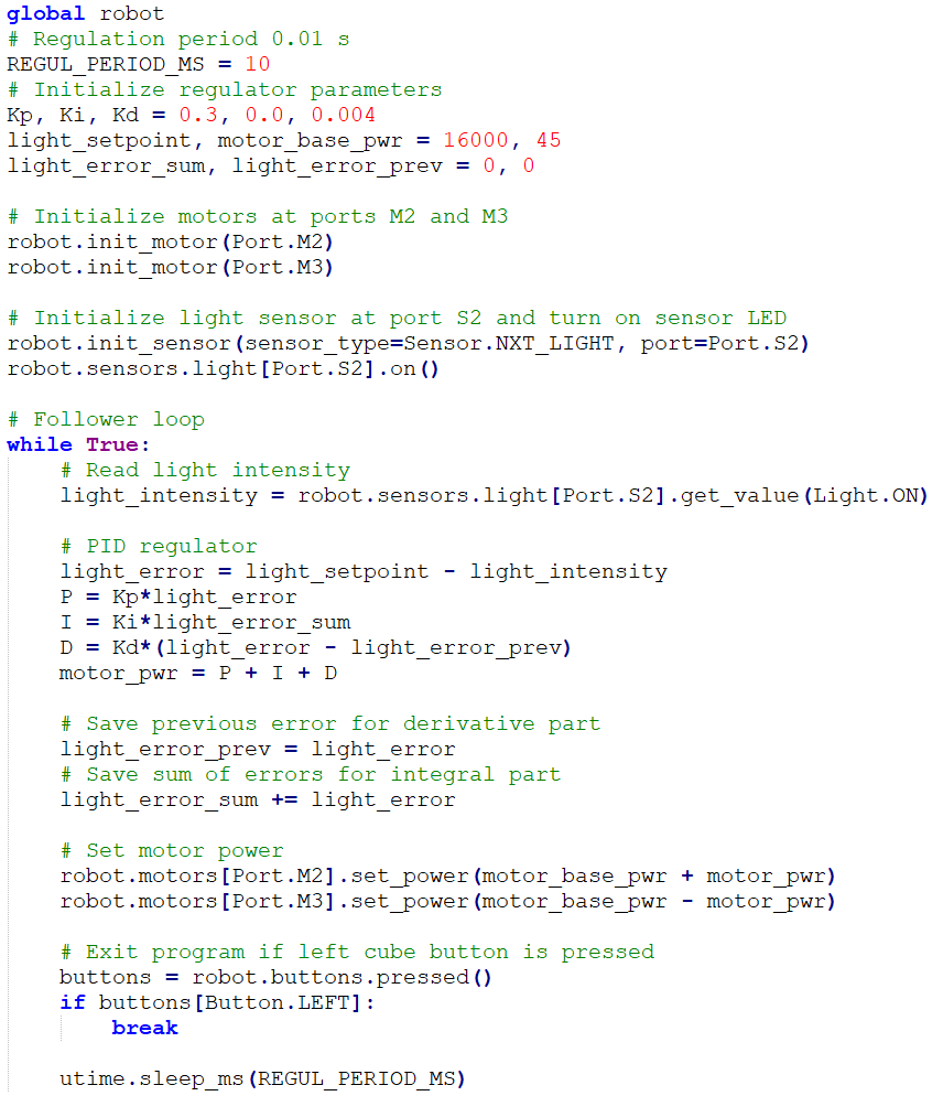
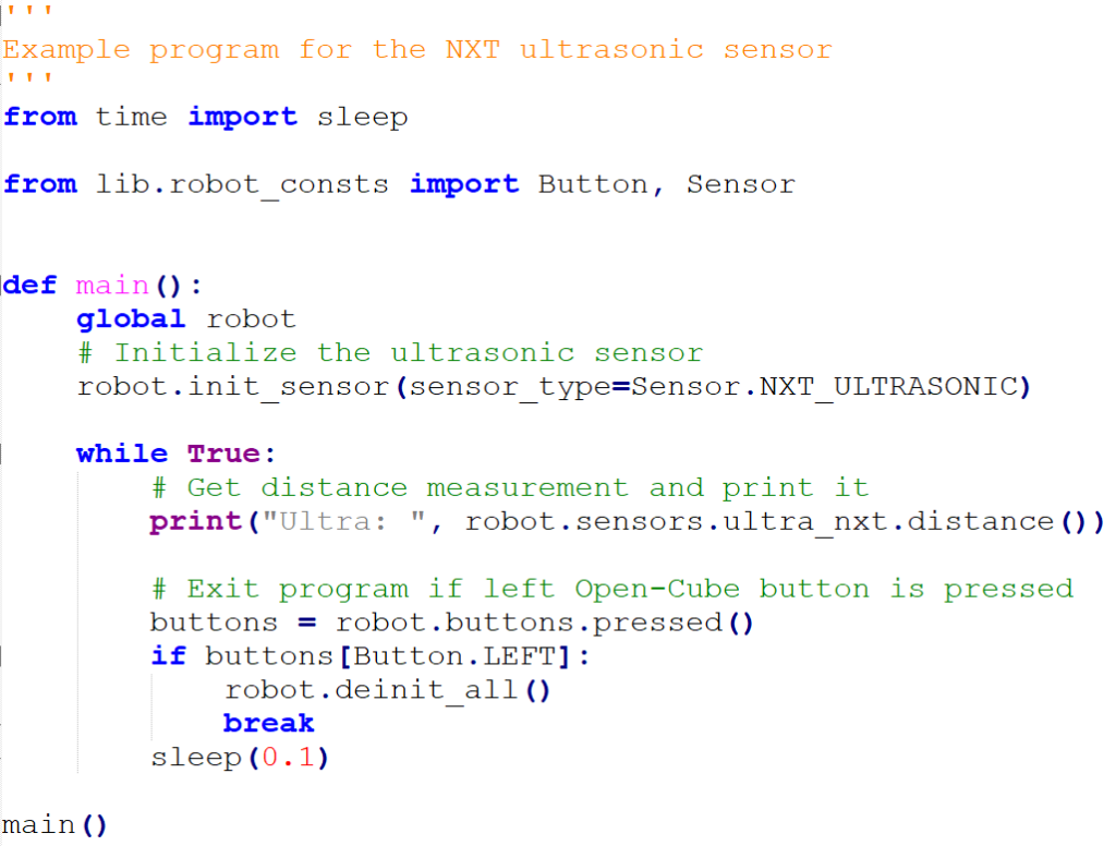
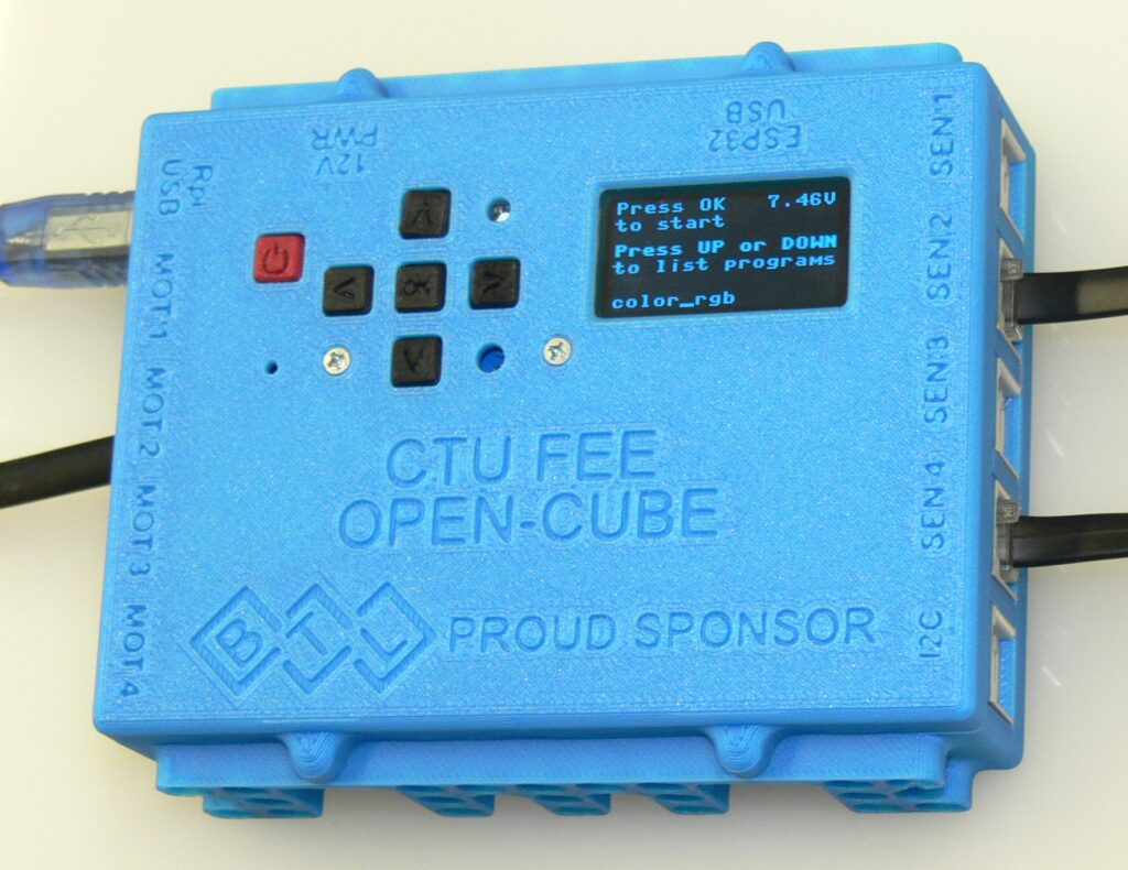
A newly developed controller for teaching/learning robotics. Compatible with LEGO NXT and EV3 components (brics, sensors and motors). Easily programmable using MicroPython. With powerful wireless communication capability – use serial Bluetooth to control it from a computer or just visualize/record internal variables, connect to its Wi-Fi hotspot with a mobile phone or tablet. It is fully open source, so you can easily add new functions or interface your own external modules, sensors and more.

BTL sponsored the production of the first series of Open-Cubes (25 units with 30+50 sensors). We are very happy to have found a company that supports multiple efforts to attract kids to study electronics/programming.

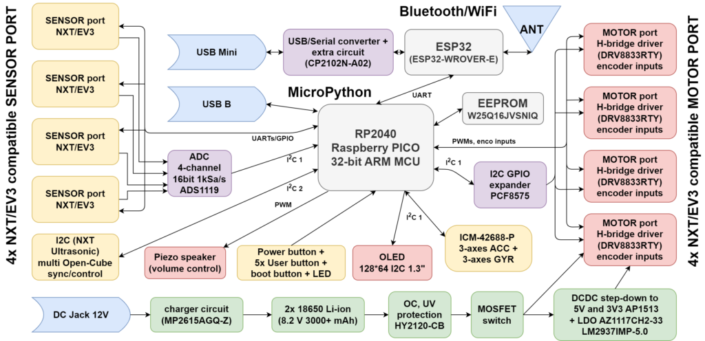
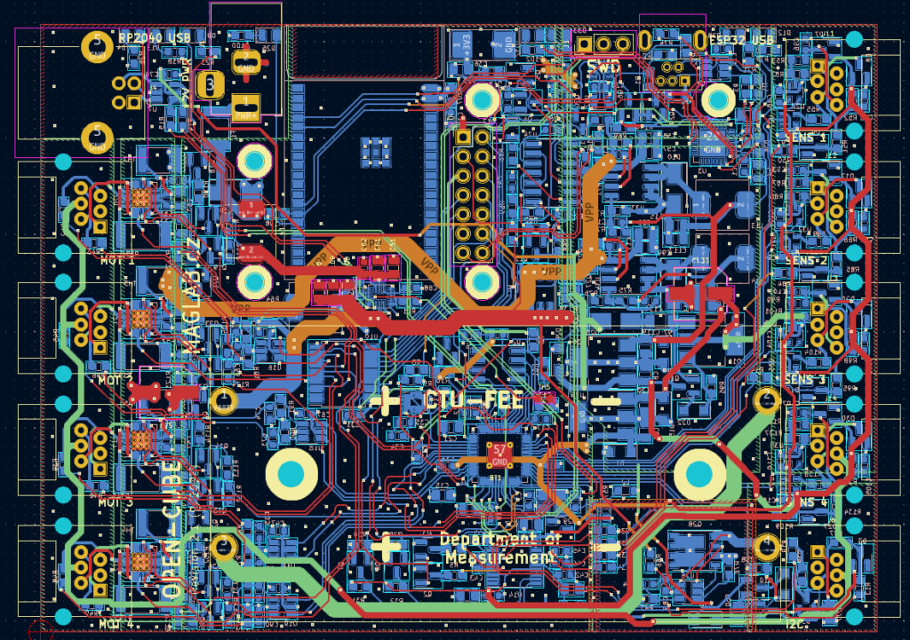
Open-Cube circuit description
The unit is powered by two 18650 Li-ion batteries. They are located in a socket, so they are relatively easy to replace by an experienced user (removal of the cover is necessary). We considered using a separate battery module (as in the case of the NXT or EV3 units), but this would add mechanical complexity, reduce reliability and increase cost in this case of a non-professional design. The battery is directly connected to the battery protection circuit (HY2120-CB) with ability to disconnect batteries and then to the charger circuit (MP2615A). The charger does not ensure the balance of two cells connected in series, therefore batteries with the same state of charge must be inserted into the module. Protection IC fights overcharge, overdischarge and overcurrent problems. So bare “unprotected” Li-ion cells can be used. The on/off function is handled by a simple circuit with two NAND gates with Schmitt Trigger inputs (CD4093BN). It allows the unit to be turned on and off with the power switch and also to be turned off from the program with Q27. A short press is handled by FW while long press of the On/Off button will turn off the unit regardless of the state of the program (which can be frozen).
Power from the batteries is fed to two DC/DC buck converters followed by two linear post-regulators. At first version we only used switching power supplies, but managed to burn the RP2040 probably due to some fault in the power rail/overshoot of DC/DC, so LDOs and Zener diodes were added to the circuit just to be safe.
The main microcontroller is a 32-bit ARM RP2040 (Raspberry Pi PICO) used for its good performance, availability and reasonable price. The external program memory and USB interface are similar to the Raspberry Pi PICO module. Most of the RP2040 PIO (Programmable Input Output) modules are used to communicate with EV3 sensors over UARTs. The RP2040 has a relatively low pin count, so a GPIO extender connected via I2C (PCF8575) is used for some “slow” signals. It enables motor drivers and controls movement direction, senses user buttons and few other things. The ESP32 is used for wireless communication with the outside world. We considered using the new ESP32-C3 version that does not need an external USB-to-serial converter, but we found BLE sub-optimal for this application and kept the “legacy” ESP32 in the design. RP2040 communicates with ESP32 over dedicated UART and an additional GPIO signal is available that allows for optional switching between data/command transfers. The ESP32 can currently be set to Bluetooth or Wi-Fi mode by the user program in RP2040, or not used at all. The ESP32 has its own USB-mini programming connector. There are four multiplexers that connect the ESP32 to a USB-to-serial converter (CP2102N) when the USB-mini is plugged into a computer to allow ESP32 programming and connect the ESP32 to the RP2040 during normal operation.
There are four identical motor ports driven by DRV8833RTY. This is a dual H-bridge IC, we connected the outputs in parallel to increase reliability when operating under heavy loads. The current limit (1A) has been tested to work well. The transistor circuit connected to the control signals allows only one PWM output and one GPIO to be used, otherwise two outputs with PWM capability would be needed.
Four identical input ports have an analog voltage measurement function on pin 1 and a GPIO/UART interface on pins 5 and 6. Two different buffers are used to protect the main microcontroller and to transmit and receive signaling at the correct levels.
An external analog-to-digital converter is used to convert the four analog inputs to a digital word. The ADS1119 offers 1kSa/s at 16bit with four-input multiplexer. With an external reference (LM4040), the ADC is accurate enough to be used as a DAQ even for more precise sensors than standard robotic Lego ones.
For compatibility with the NXT Ultrasonic sensor, a specific port (I2C) is used. With the possibility of activating an extra stronger pull-up resistor for communication at a higher frequency (100 kHz), the port can be used, for example, to control or synchronize multiple units to solve more complex tasks.
Directly on the board there is a 6-axis MEMS Motion Tracking IC, accessible via the I2C bus. Well suited for stabilizing a balancing robot or simple motion (rotation) control.
The OLED display, user buttons, LED and PIEZO are on a separate PCB sub-panel. The volume of the piezo can be adjusted with a resistor trimmer, by changing the PWM duty or frequency (the transfer function is not very flat).